Intro to SDR and RF Signal Analysis
Visual analysis of signal characteristics using software-defined radio
Visual analysis of signal characteristics using software-defined radio
The increasing popularity of Internet of Things (IoT) and other devices becoming wireless is very much apparent in today’s society. With availability of modern Software Defined Radio (SDR) hardware, it has become more accessible, cheaper, and easier than ever to examine the Radio Frequency (RF) signals that are used by these devices to communicate. The following discussion attempts to understand how this communication information is transmitted through RF, and how SDR may be used to analyse and possibly reverse engineer this signal back to understandable data. To achieve this, the RF signals of a number of simple household RF devices will be examined visually in an effort to identify the characteristics of the transmitted signal, along with the data that was transmitted.
To talk about RF, we first have to have some understanding of electromagnetic radiation (EMR). When a charged particle is accelerated through space, such as being emitted by an antenna, it produces two oscillating fields that occur perpendicular to each other, an electric field, and a magnetic field. These oscillating fields are called an EM wave, and can be visualised as shown in the following image, where x is time, E the electric field, and B the magnetic field.
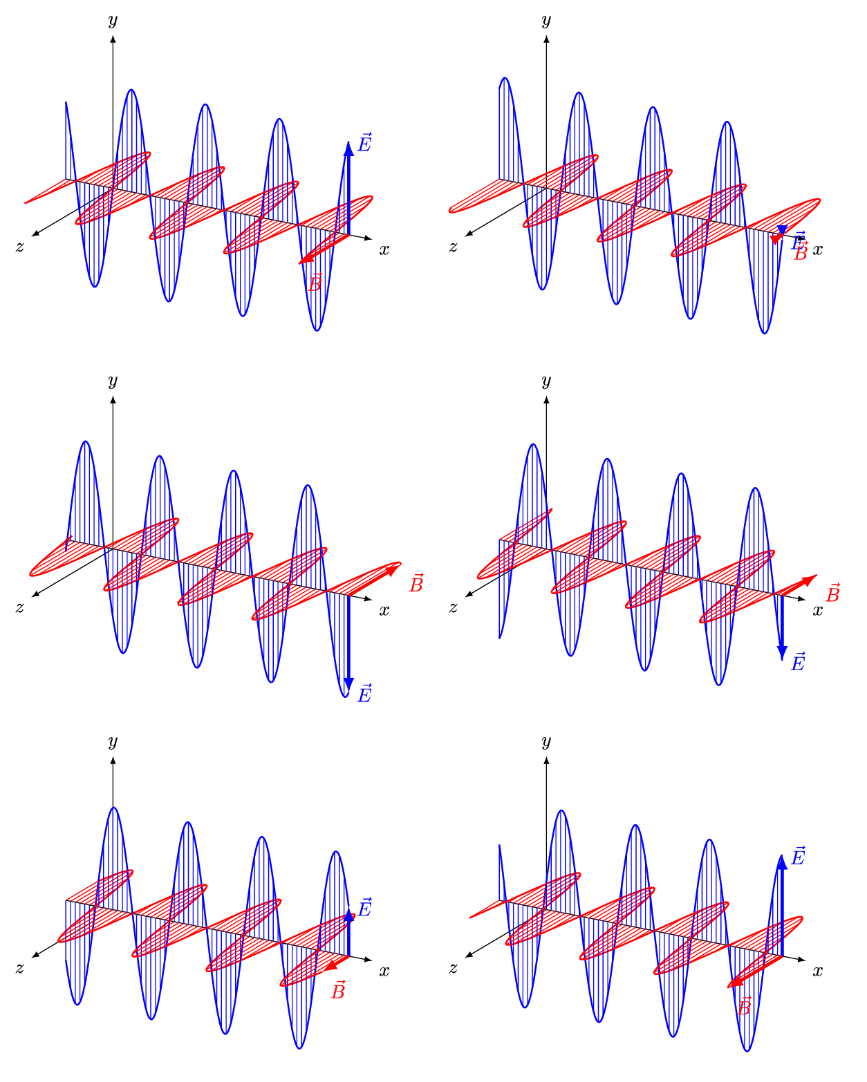
You already know EM waves because we deal with them on a daily basis. Radio waves, microwaves, infrared radiation, visible light, ultraviolet light, x-rays, and gamma-rays, are all EMR. The difference between these types of EMR is the frequency range in which the EM waves oscillate.
RF is generally thought of as EMR with EM wave frequencies in the range of 3kHz to 300GHz, and is mostly used for RADAR and wireless communications. An easy example of RF communication is WiFi, which operates in the 2.4GHz and 5GHz frequency ranges.
For our purposes, we will need to identify a few basic characteristics of EM waves in order to analyse a given signal. These are frequency and wavelength, amplitude, and phase.
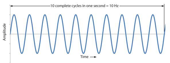
As previously discussed, the frequency of a wave is the rate at which it’s EM fields are oscillating. Generally, the electric field is measured, in which a wave cycle is the oscillating pattern of the wave before that pattern repeats. Frequency (f) is therefore the number of EM wave cycles that occur within a given unit of time. This is generally measured in Hertz (Hz), which is the number of wave cycles per second. This can be seen in the following image, which shows a ten wave cycles of a signal with the frequency of 10 Hz.
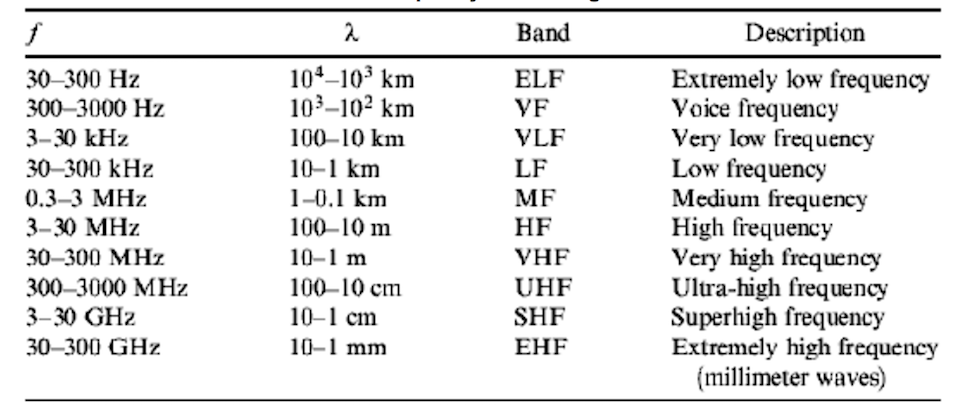
Frequency also has a close relationship with the wavelength (λ), which is the distance the wave travels in one wave cycle. As EMR travels at the speed of light (C) through a vacuum, frequency and wavelength are inversely proportional. To calculate this, the formula (λ = f / v) may be used, where v is the velocity in a given medium, generally around 300,000 kms/s (approx. speed of light in a vacuum). Frequency is further categorised into frequency bands, which can be seen the following image, also showing the relationship between frequency and wavelength. Why is wavelengthimportant you ask? It directly relates to choosing an appropriate antenna length for a given signal, which we will cover later.
Frequencies are chosen depending on the needs of an application, for instance lower frequencies tend to propagate longer distances than higher frequencies, and is used in applications like over-the-horizon RADAR. Similar frequencies can also interfere with each other, hence why radio stations are separated in frequency. Many countries have government bodies that control the RF spectrum to avoid interference between applications, and regulate RF use. Within Australia, this is the Australian Communications and Media Authority (ACMA). An example of this spectrum allocation can be found here. Only a small portion of the RF spectrum allows transmission without the need for a licence.
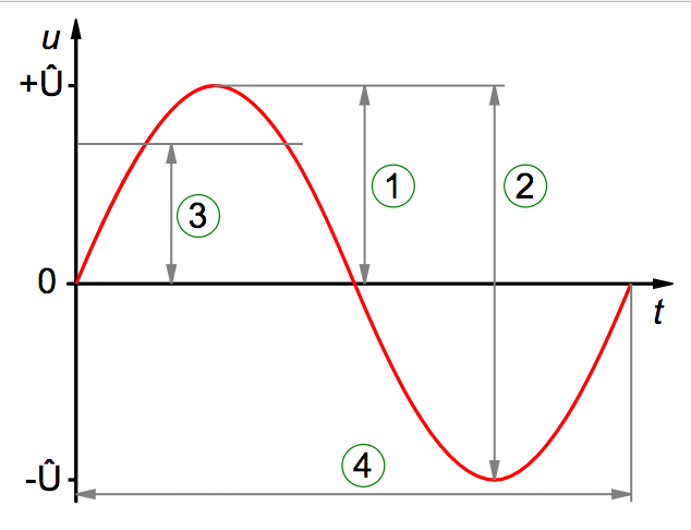
The amplitude of an RF signal can be thought of as a measure of the change in the electric field oscillation over a a single period. For a sinusoidal wave, this is the magnitude the wave swings above and below a reference value, and can be measured in a few ways, such as peak, peak-to-peak, and root mean square (RMS) amplitude. These are shown in the following image as items 1, 2, and 3, respectively.
For our purposes, we will only need to observe the changes in amplitude of signals and won’t need to measure this value, however within telecommunications this value is usually a measure of voltage, current, field intensity, or power.
Lastly let’s have a look at the phase characteristic of an RF signal. The phase of a wave can be thought of as the position of a single point in time during a wave cycle. For a sinusoidal wave this is usually expressed in degrees, or radians, which is shown in the following image.
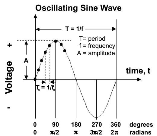
As you can see, if a wave was shifted 180 degrees out of phase, it would be the complete opposite of the original waveform.
To be useful for any form of communication, an RF signal must have a way to carry information. The previous three wave characteristics, frequency, amplitude, and phase, make up the building blocks for modifying an RF signal in some way to carry data. This is called modulation, and involves mixing a modulating signal, which contains the information to be transmitted, into a periodic waveform called the carrier wave (CW), which propagates the signal through the environment.
Analogue modulation involves sending an analogue data signal, with an analogue carrier wave. Examples of this would be analogue TV or radio station transmissions. There are a few analogue modulation schemes, however the simplest are amplitude, frequency, and phase modulation.
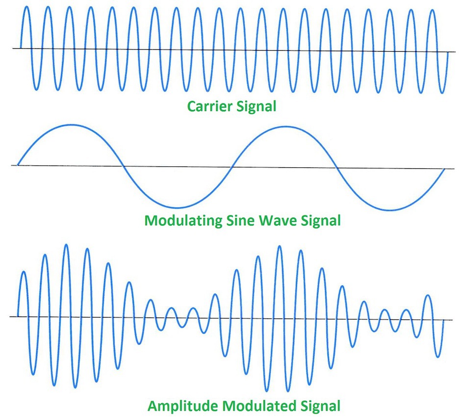
With amplitude modulation, the amplitude of the carrier wave is modulated with the data signal. This can be seen in the diagram below
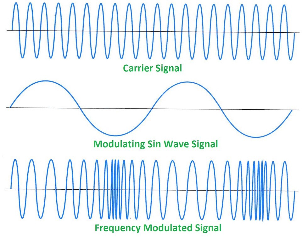
Frequency modulation can be seen in the diagram below, and shows how the data signal is used to modulate the frequency characteristic of carrier wave.
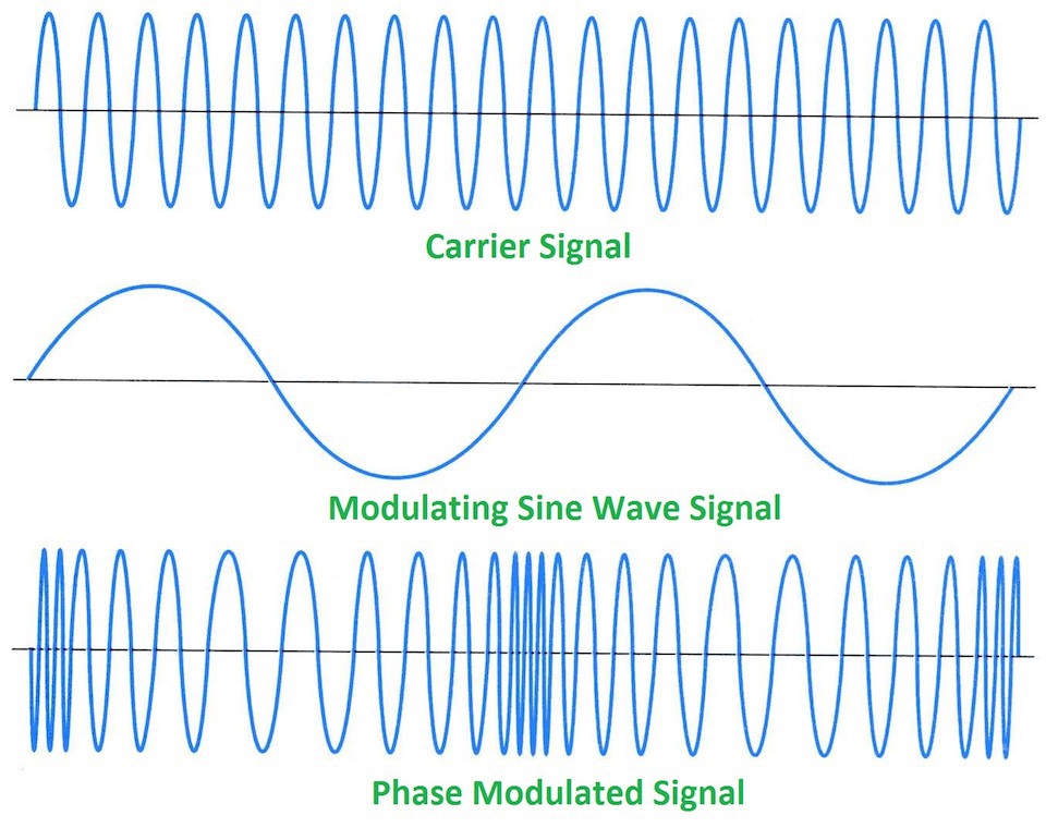
Analogue phase modulation looks very similar to frequency modulation and may be difficult to differentiate the two without some prior knowledge of how the signal is modulated. With this modulation, the carrier wave’s phase is either pushed forward or backward by the modulating data signal.
Digital modulation comes from the need to represent a digital signal, i.e. ones and zeros, in the analogue medium of RF for transmission. To achieve this, discrete RF energy states are used to representing some quantity of the digital information, these are called symbols. The three most basic modulation schemes for transmitting digital data are Amplitude Shift Keying, Frequency Shift Keying, and Phase Shift Keying.
ASK involves using the digital data to modulate the amplitude of the carrier wave. This may be by altering the amplitude itself, or simply turning the signal off and on forming a pulse of energy, which is called On-Off Keying (OOK). The following image shows how binary data might modulate the carrier wave through ASK and OOK.
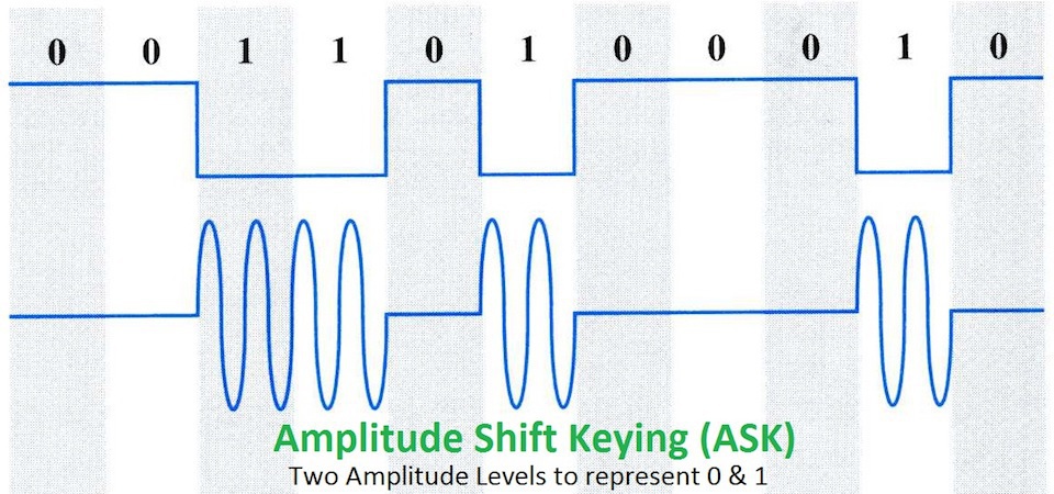
Many forms of RADAR transmit pulses of energy like this, then listen to for the weak reflection of the pulse in order to determine the position of objects in an environment.
Similar to ASK, FSK modulates the frequency of the carrier wave with the binary data, forming symbols that have distinct changes in frequency to represent the bits, as seen below.
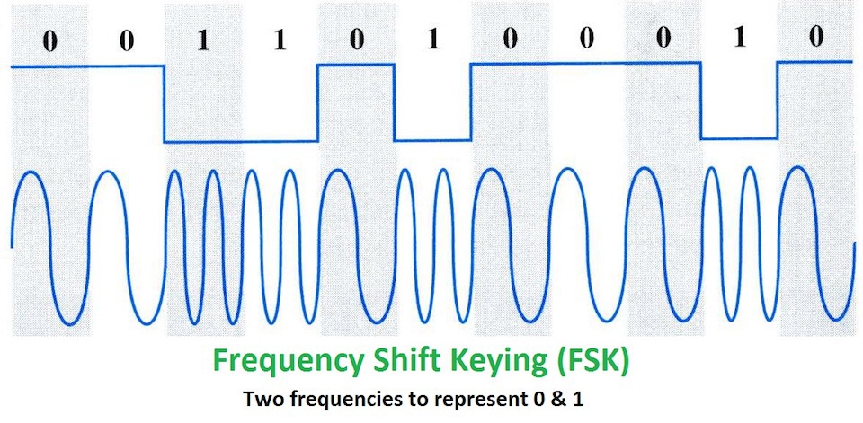
Finally, PSK uses the digital data to modulate the phase of the carrier wave, and forms distinct angular changes in the phase of the signal to represent the binary data as a symbol.
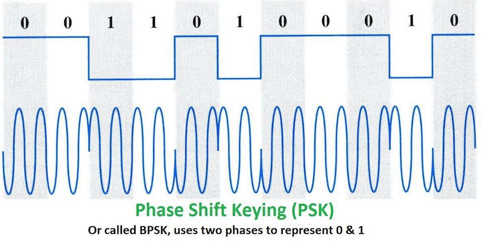
Knowing what we just learned with respect to basic modulation schemes, can you identify the modulation used in the following captured signals? Which are analogue and which are digital?
Note: The animated gif of each signal shows a waterfall plot of time vs. frequency (higher amplitudes also showing as a brighter green) at the top, with a plot of amplitude vs. frequency at the bottom. The image that follows each animated gif shows a subsection of the waveform which represents the wave’s amplitude vs. time.
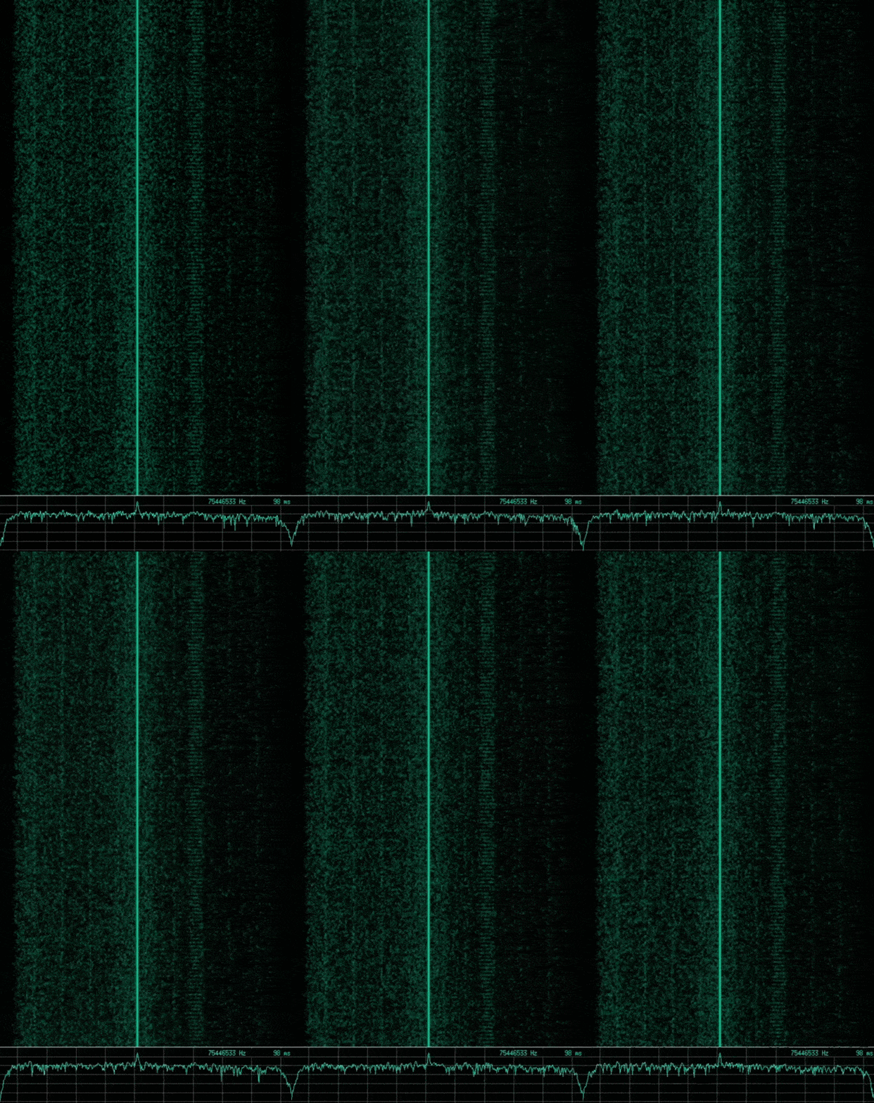

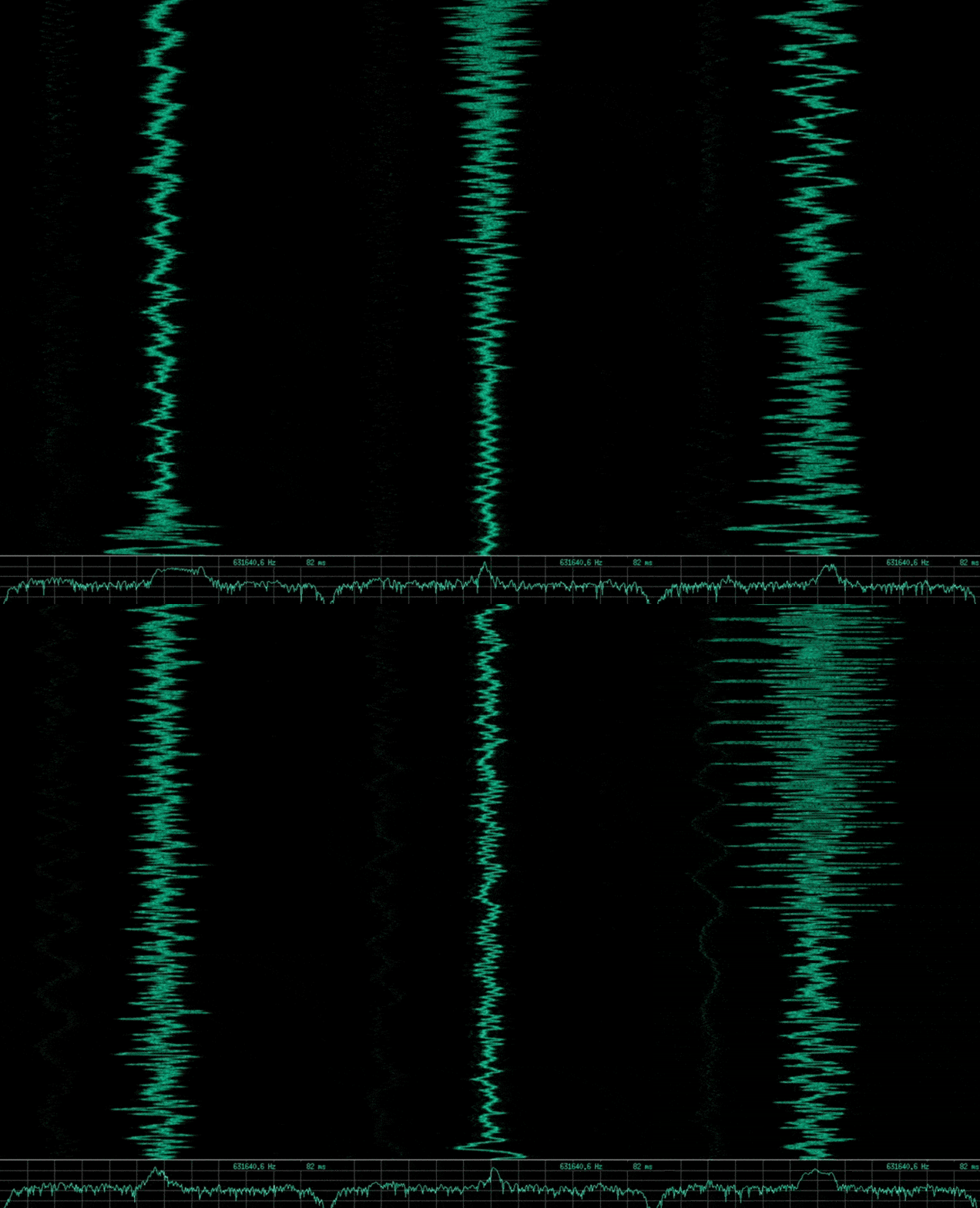

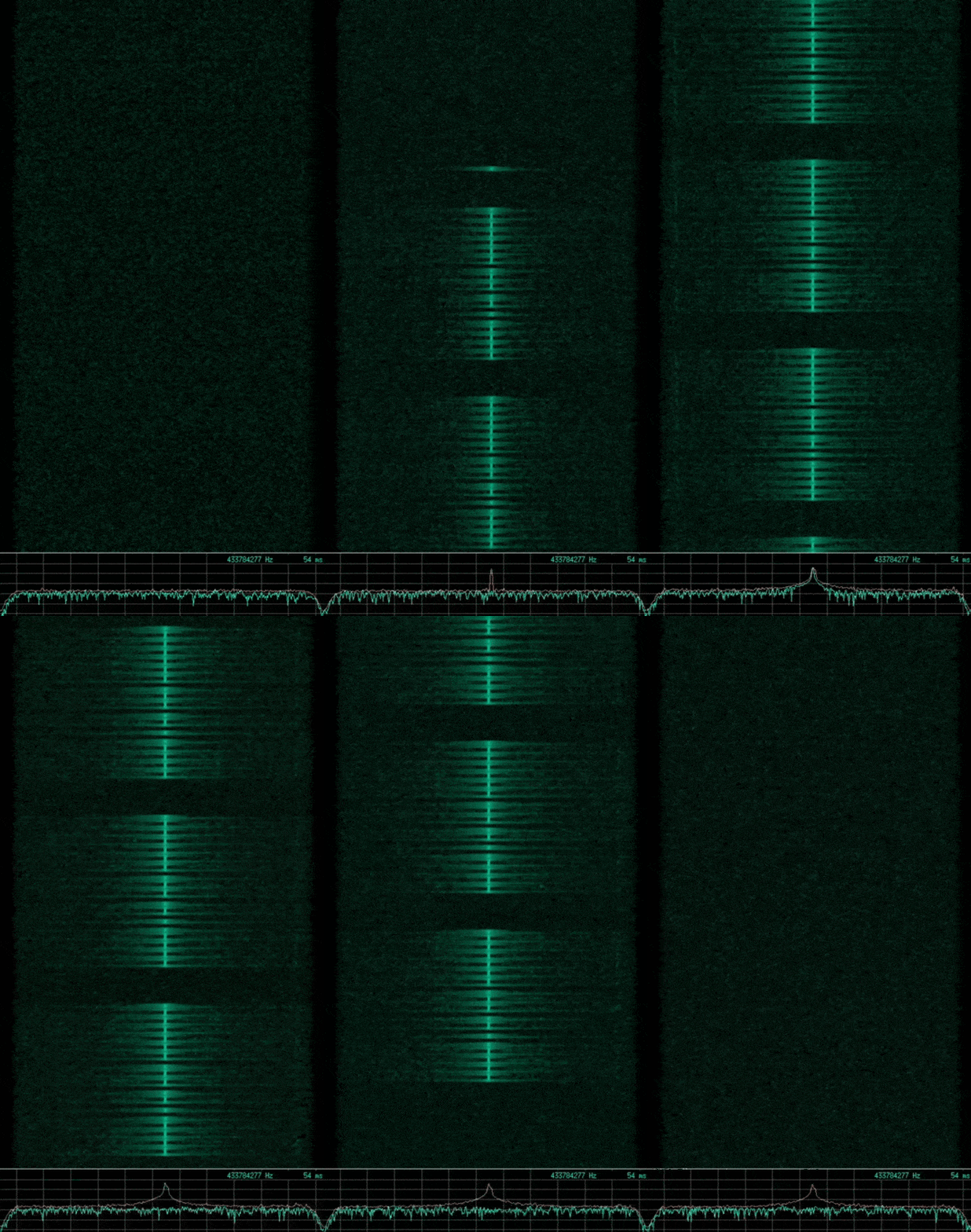

If you said the first is AM, the second is FM, and the third is ASK or OOK. Then you are correct, however the third signal implements a slightly more complex type of ASK, known as Pulse Duration Modulation (PDM) where the duration of the pulse relates to the modulating data.
Even with high speed systems, transmission of digital data in a format where a symbol represents a single one or a zero is very slow. To increase the speed of data transfer, more complex forms of modulation are used, in which a single symbol represents several bits. To give an idea about how this might be implemented, we will quickly look at Quadrature Phase Shift Keying (QPSK) and Quadrature Amplitude Modulation (QAM) which are the modulation components of WiFi signals.
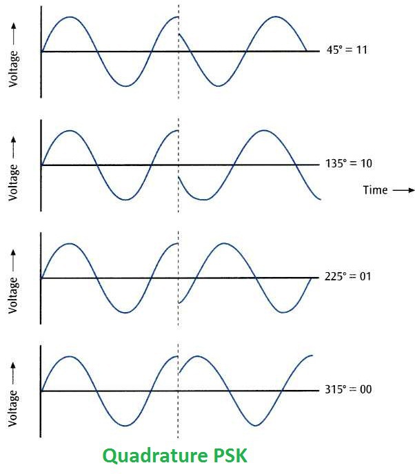
QPSK involves modulating the signal to achieve four distinct phase shifted symbols, each representing a combination of two bits, as shown in the following image.
This can be visualised by plotting the points on the circular nature of the sinusoidal pattern, shown in the diagram below, where the I plane represents the in-phase component, and Q the quadrature.
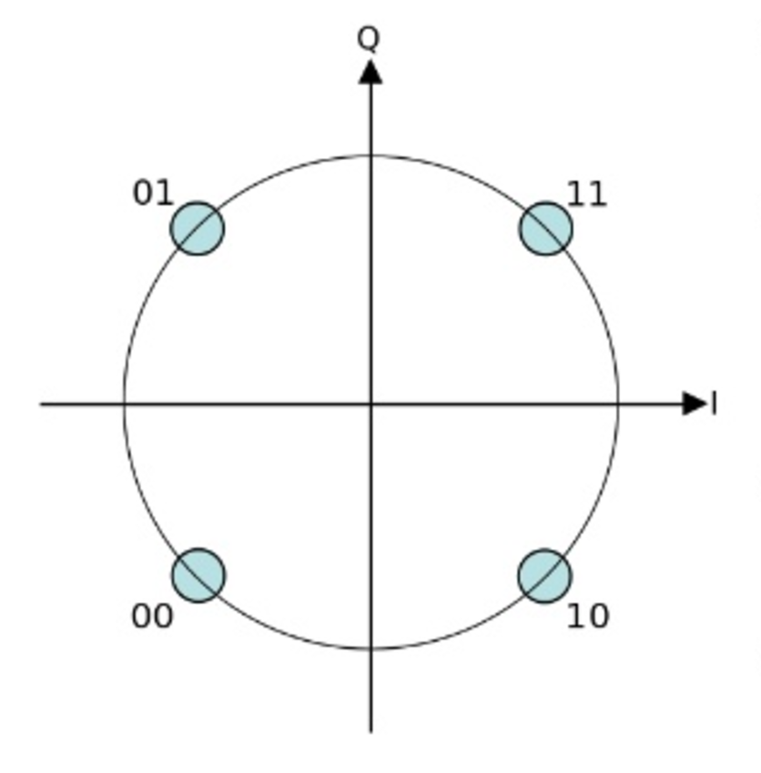
Further modifications of this exist that add more phase points, such as 32-PSK, which produces more distinct symbols, and increases the data rate.
QAM furthers the concept of QPSK by adding the modulation of amplitude in addition to the phase of the signal. A good example of this can be seen in the following image, which shows 16-QAM.
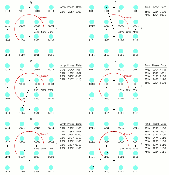
Here you can see there are sixteen distinct symbols, each relating to four bits of binary data.
In combination with digital modulation, transmission of the data can be spread across multiple frequencies, this is called spread spectrum. This is used to reduce the effect of interference and possibly make the signal more difficult to detect, as it appears similar to noise. Two common forms of spread spectrum are Direct Sequence Spread Spectrum (DSSS), and Frequency Hopping Spread Spectrum.
DSSS takes each transmitted bit and represents it with multiple bits called a spreading code, which is transmitted over a wide frequency range.
FHSS hops the transmission between a predetermined set of frequencies, in which the receiver is synchronised with the transmitter.
The example signals above were captured using a hardware SDR device, and displayed using signal analysis software, Baudline.
As radio equipment can be very expensive, and is usually specific to particular applications, SDR solves this problem by removing components that would usually be implemented in hardware, such as mixers, amplifiers, modulators, and demodulators, and implements them in software. This means we can analyse the raw signal being received, however it is up to us to implement the other components in software in order to retrieve the original data. Doing this requires a deeper understanding, but for our purposes we will use inexpensive SDR hardware and software to take a look at some captured signals, and have a go at visually analysing them.
There a several good and relatively inexpensive SDR hardware devices on the market that can be used to receive and transmit RF. The ones used here are the following:
The software tools I found most helpful for capturing and analysing RF signals on a Linux platform are as follows:
All these software tools are free, and there are many more out there, including a lot that can automatically demodulate data for specific RF systems.
Note: SDR can be quite resource intensive, the amount of data that is captured in a small time frame can be very large, and also requires high bandwidth from the USB port your SDR device is attached to. This can also cause issues if using virtual machines. There is plenty of information online about setting up SDR devices and software, so Google is your friend here.
Because SDR converts the analogue signal received into digital data, something to note here is the concept of samplerate, and bandwidth. Samplerate refers to the number of samples taken of the analogue signal per second, and directly relates to the bandwidth of the frequency spectrum that is visible at any particular point in time. For example, the higher the samplerate the more frequencies you can see, however this also increases the amount of data being received. The samplerate that is possible depends on your SDR device and the ability of your particular computing resources. Gain is also another important concept, and relates to the amplification of signals. It is worthwhile having a read about these with respect to your particular SDR device.
To start to view and analyse a specific RF signal, I found the easiest way, with my particular resources, was to pipe the data received from the SDR device into Baudline. This is quite simple with both an RTL_SDR device or the HackRF, using their CLI commands rtl_sdr, or hackrf_transfer respectively, however some characteristic of the particular device need to be known. Both RTL_SDR and HackRF use two channels to sample the quadrature values I and Q previously talked about. In the case of the HackRF, the samples are 8-bit signed values, and this needs to be relayed to Baudline in order to correctly interpret the data. To make this easier, I wrote the following bash script to pipe the HackRF output to Baudline and allow real-time viewing of the spectrum:
#!/bin/bash
# ./hackrf_baudline.sh <frequency> <samplerate> <ifgain> <bbgain>

# Pipe HackRF output to Baudline
hackrf_transfer -r - -f ${1} -s ${2} -l ${3} -g ${4} | baudline -reset -basefrequency ${1} -samplerate ${2} -channels 2 -format s8 -quadrature -flipcomplex -stdin
For example, running ./hackrf_baudline.sh 100000000 8000000 24 20, might give you something similar to the following image in Baudline.
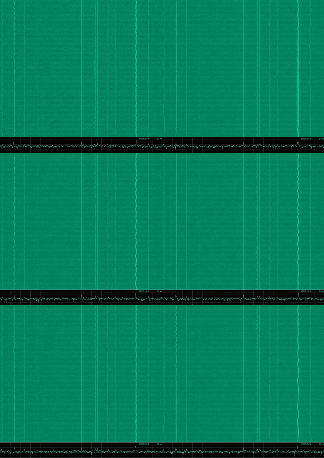
There is some noise here in my set up, however this shows a portion of the RF spectrum around the centre frequency of 100 MHz. For me there are several FM radio stations in this range that are visible.
Note: Something to mention here is that you can see a constant distinct signal right at the centre frequency. This is called the Direct Current (DC) offset, and is an artifact of the measurement system that is implemented in the device. This is apparently common in all quadrature sampling systems, however it seemed particularly pronounced with the *HackRF. The easiest way to deal with this is to offset the centre frequency slightly from the frequency you wish to analyse.*
osmocom_fft is also very useful for looking at large portion of the RF spectrum in order to identify a particular signal, however baudline appears to have a lot more features for analysing signals. Although many of the features I have no idea what they do, some of the ones I found useful are as follows (usually found by right-clicking within a baudline window):
Both baudline and osmocom_fft have the option to save to a file, and this is also possible straight from the RTL_SDR and HackRF command line tools rtl_sdr and hackrf_transfer.
Note: A quick note here on antennas. Antenna theory is a whole science in itself, however to improve the received signal, it is a good idea to use an antenna that is quarter wavelength of the desired frequency to receive. For a telescopic antenna this may be as simple as extending it to approximately to correct length. Quarter wavelength in centimetres can be approximated by dividing 300 by the frequency in MHz, multiplying by 100, and dividing by 4.
Another useful tool here is Inspectrum. With Inspectrum you can load and view the frequency spectrum captured through the use of one of the other tools, however it offers a nice cursor function that allows you to easily identify the symbols and the symbol rate, otherwise known as baudrate. You can see the use of this in the garage door example in the later sections.
If your ultimate goal is to reverse engineer an RF signal and understand it’s protocol, a nice methodology to follow can be found in a Hack In The Box (HITB) conference talk by Matt Knight and Marc Newlin, which can be found here HITB 2017 - So You Want to Hack Radios?.
It discusses the following steps:
For our purposes of visually analysing some RF signals, we will mainly look at aspects of steps 2-5.
First, we will take a look at a cheap wireless doorbell system purchased from a local electronics store. Specifically, the RF signal that the doorbell remote transmits to the doorbell receiver.
The doorbell remote in question can be seen in the following image.
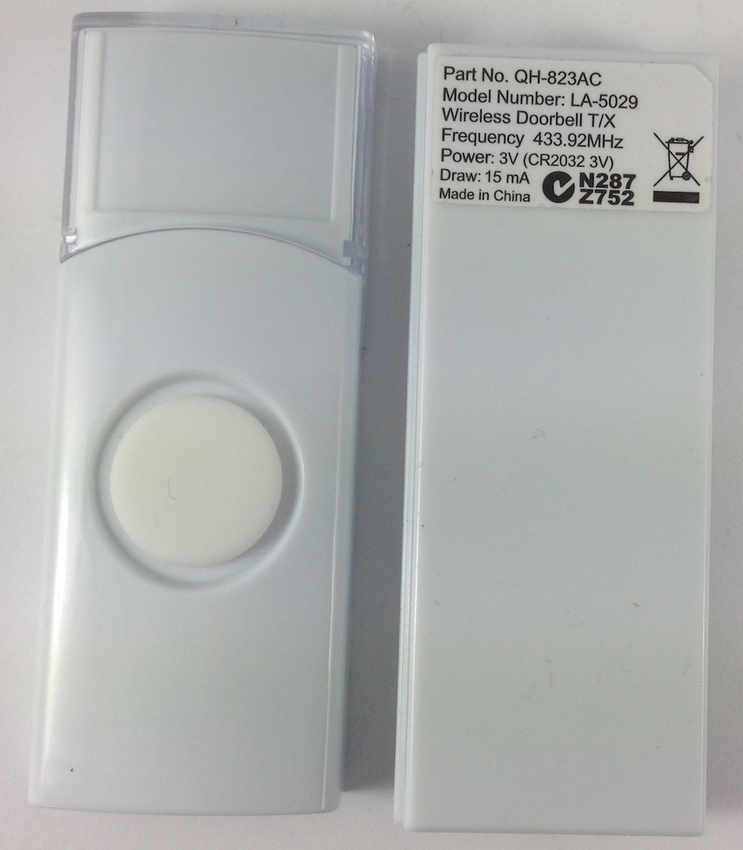
Already we can determine its operating frequency just by looking at the back of the device, 433.92MHz. The part number and model number are also seen here, which may be useful for some online OSINT. Opening up the device, further information can be found, as shown in the following image.
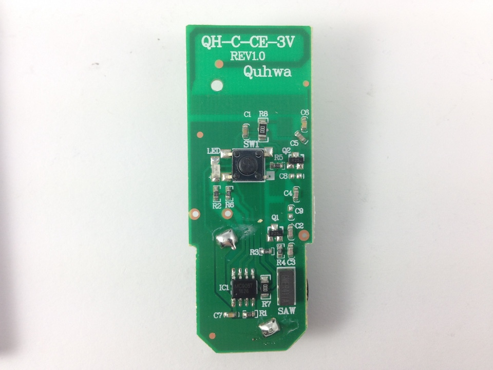
To avoid ruining the surprise, no further OSINT was performed on the device. We can now fire up the HackRF with baudline to take a look at the RF signal produced when pressing the button of the doorbell remote. Using my previously mentioned script to pipe the received data to baudline, we can enter arguments to ensure we are in the correct frequency range to be viewed. Something like ./hackrf_baudline 433000000 8000000 24 20. Using the functionality of baudline we can zero in on the signal when the remote’s button is pressed. A waterfall plot of this signal can be seen in the following image.

With this we can now characterise the channel, it’s operating at the base frequency of 433.92 MHz and has a very narrow bandwidth. Knowing the basic characteristics of a EM wave, what else can we tell about this signal? Its amplitude is changing, in fact, the signal appears to be pulsed on and off, so this is likely to be a form of ASK with OOK. It also appears to be a number of repeating packets with short gaps between. Within baudline we can pause the output, and take a closer look at the signal. Opening up the waveform window, we can now scroll through the entire transmission, in which we can each packet has the same sequence of OOK, as shown in the image below.

We can now clearly see that this is OOK, however there is a definite short pulse and a long pulse visible, so it is most likely PDM and answers our modulation question.
We need to work out the symbol rate, so in this case we see there are two distinct symbols used to represent different information. One might be a short gap with a long pulse, the other a long gap with a short pulse. You can use the previously mentioned delta selected functionality of baudline to measure the time of these symbols and calculate how many would occur within one second to determine the baudrate (1 baud = 1 symbol per second). However, in our case we might want to transmit this signal later and need to represent each symbol with 1’s and 0’s, for instance the short pulse symbol may be represented by 0001. For this, we will measure the shortest pulse or gap that appears. Using the shortest pulse, we get a baud of 2960.
So, knowing this is PDM, we can assume that a short pulse may represent a 0, whilst the long pulse may represent a 1. With this assumption, we can now say that the doorbell transmits multiple packets of the binary data 011111101101001111 on each click of the button. Capturing another click of the remote, the sequence does not change.
Also notice there is a short pulse at the very start, shown in waveform above, before the sequence of repeating packets. This is most likely some kind of synchronisation for the receiver, not exactly a preamble, but something.
So, what do we know about this RF signal now?
011111101101001111As there is no keying and only one button on the remote, we’re unable to determine the structure of the packets without another device. However, let’s go ahead and test what we know by transmitting our own data, and attempting to ring the doorbell. In this case we can use the YardStick One USB device to transmit data sent to it with rf_cat, a similar tool to netcat for RF. To do this we can write a python script to interact with the YardStick One and send our data.
We will need to represent the data with respect to the baudrate. So as previously mentioned, for our assumed symbol representing 0 (a long gap with a short pulse), we will need to transmit 0001. For the symbol representing 1, we will need to transmit 0111.
Other considerations are the gap between packets, which was measured to be four symbols in duration, and also the synchronisation pulse that appears, which was measured to occur four symbols prior to the first packet.
The resulting python script can be seen below.
#!/usr/bin/python
import sys
from rflib import *
import bitstring

baseFreq = 433920000 # 433.92 MHz
baudRate = 2960

key = '000101110111011101110111011100010111011100010111000100010111011101110111'
pad = '0000000000000000'

d = RfCat()
d.setMdmModulation(MOD_ASK_OOK) # Setting the modulation
d.setFreq(baseFreq)             # Setting the TX frequency
d.setMdmSyncMode(0)             # No sync mode
d.setMdmDRate(baudRate)         # The symbol rate
d.setMaxPower()                 # Max Power, YOLO!
#d.setPktPQT(0) # Preamble Quality Threshold

full_pwm = '{}{}'.format(key, pad)
rf_data = bitstring.BitArray(bin=full_pwm).tobytes() # Convert to bytes
d.makePktFLEN(len(rf_data))                          # Set the packet length in bytes
print "Transmitting key {}".format(rf_data.encode('hex'))
print "Packet length: " + str(len(rf_data))

d.RFxmit('\x00\x01\x00\x00') # TX synchronisation pulse
d.RFxmit(rf_data, repeat=30) # TX repeated packets

print "Done."
d.setModeIDLE()Another device looked at was a very old and as you will see, strange, wireless garage door remote. Looking at the device, we can again quickly determine the operating frequency, 26.995 MHz, as shown in the image below.
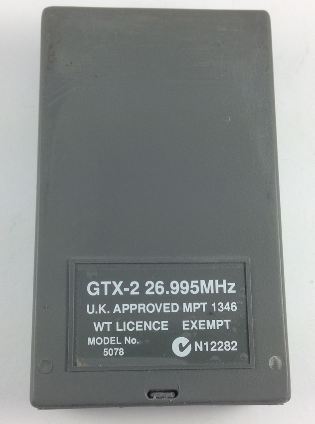
This is not a commonly used frequency for these types of devices anymore, in fact the antenna length needed for this is bigger than my telescopic antenna can go, however this is not too much of an issue. The internals of this device reveal it includes the ability to set a code via DIP switches in order to pair it with the garage door receiver, shown below.
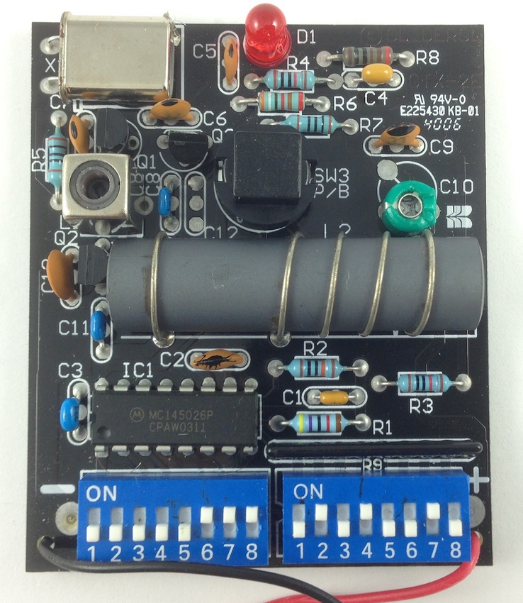
Note: That big cylinder in the centre is a ferrite coil antenna, and clearly this device was made in an era where electronic components were much bigger
Again, without doing any further OSINT, we take a look at the signal this produces with the help of HackRF and baudline. The first thing to notice is that the signal only transmits while the remote’s button is held, and will transmit constantly. This can be seen below.
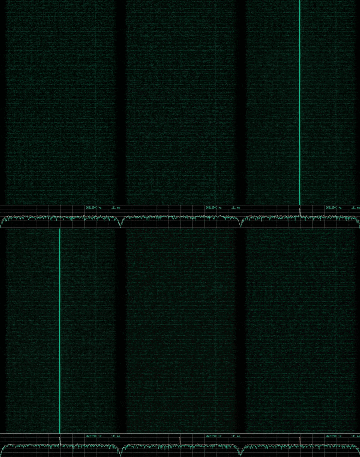
Again, no apparent change in frequency, and a narrow bandwidth signal. Taking a look at the waveform, we can see the following.

Looking at this, there is no change in phase but appears to have subtle changes in amplitude. So this is most likely ASK. Within baudline I modified the aperture color in order to see the changes in amplitude more clearly on the waterfall plot, but was unsuccessful. I decided to save this signal and load it into Inspectrum, where I was more successful in viewing the amplitude changes. Fiddling with the Power Max and Power Min settings I was able to eliminate all but the highest amplitude, and started to see a repeating pattern of packets. One of these packets can be seen below.
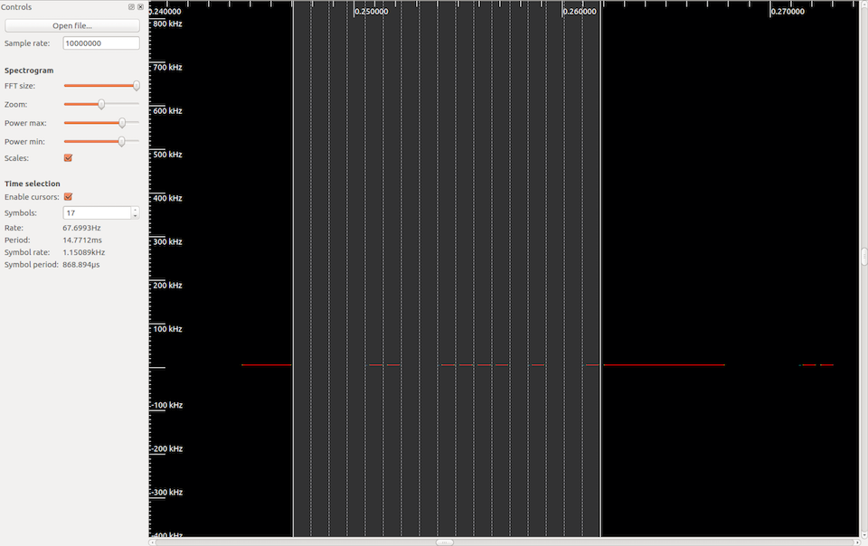
Each repeating packet was the same, and there was no change with repeated presses of the garage remote button. Enabling the cursors functionality helped here to discern the high and low amplitudes, along with the symbol rate. Assuming a low amplitude represents a 0 and a high amplitude represents a 1, the packet data appeared to be 00001100111101001. However, I was more interested in how this related to the DIP switch positions inside the device.
There are sixteen DIP switches, in two sets of eight, which I thought might relate directly to the 16+1 apparent symbols. I set all the DIP switches to their lower positions, which I will call the 0 setting, and take another look at the signal. This time we get the following.

OK, so we’ve added some 1’s, and the seventeenth symbol remained a 1. Let’s try setting the first DIP to its high setting. We get the following.

Alright, so symbol position two went to a 0, and again the seventeenth symbol remains the same. Let’s try the first DIP in the second set of eight DIP switches.

There is no change from all the DIP switches off, in fact changing any of the second set of eight DIPs would produce the same result.
Again, trying just the first DIP, and adding the second DIP, we get the following.

Now we are seeing some relationship, the first DIP seems to relate to the second symbol position, while the second DIP seemed to relate to the twelfth position. Trying each DIP switch of the first set of eight DIPs, which I will call set A, I am able to determine the following relationship to the symbols.

At this point, this seemed to be a simple mapping of the DIP to a symbol, however when trying DIP A1, with the first DIP of the second set of eight, which I will call set B, the relationship seemed to become a little more complex. This is shown below.

Notice now, we have a 1 in the first symbol position, and also in the second position, which we were expecting to be 0. It seemed the DIP B1 modified the resulting value of DIP A1. Trying this with the other corresponding A and B DIPs produced the same respective result.
After playing around with this, I realised I could describe this modification, and the result of the symbol position with respect to the A and B DIP switch pairs, with some discrete mathematics. This can be seen in the following table.
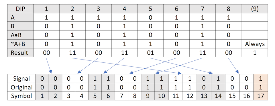
To explain this table, A and B refer to the respective DIP switch positions, 1 being high and 0 being low. A*B refers to each odd symbol, and is the binary AND of DIP A and B. Whilst ~A+B refers to each even symbol, and is the binary OR of NOT A and B.
With the original DIP positions of 11110111 01010010, we see the result of 00110011010011001, however this does not correspond to what we saw when analysing the signal, which was 00001100111101001. This because we still need to apply the previous relationship we first noted between the A DIPs and their symbol position. Doing this, shown by the blue arrows above, we can now see the result of our discrete math now corresponds correctly.
Given a captured signal from this garage remote, I am now reliably able to determine each of the sixteen DIP switch positions without ever seeing them. From here I would have liked to attempt to transmit this signal in a similar manner to the doorbell, however the YardStick One is unable to transmit on that particular frequency. However, as the transmitted data never changes, this garage door system should be vulnerable to a replay attack, in which the signal is simply recorded and retransmitted. The HackRF has the ability to do this.
Another system that we will take a look at is a very common security system that seems to be used for many homes, and businesses. This is a relatively modern system, that incorporates multiple sensors, alarms, and a polling to the security company’s monitoring service. This system includes a keypad to arm and disarm the alarm, however it also includes a number of remotes that allow the arming and disarming of the security system from outside the building. This is what we will briefly look at.
In this case the, the key did not blatantly display the operating frequency of the device, however it was very simple to discover in the RF spectrum, as it operated in the 433 MHz range, similar to the doorbell remote, which is common for these types of remotes.
Having a look at the signal in baudline, we see the following.
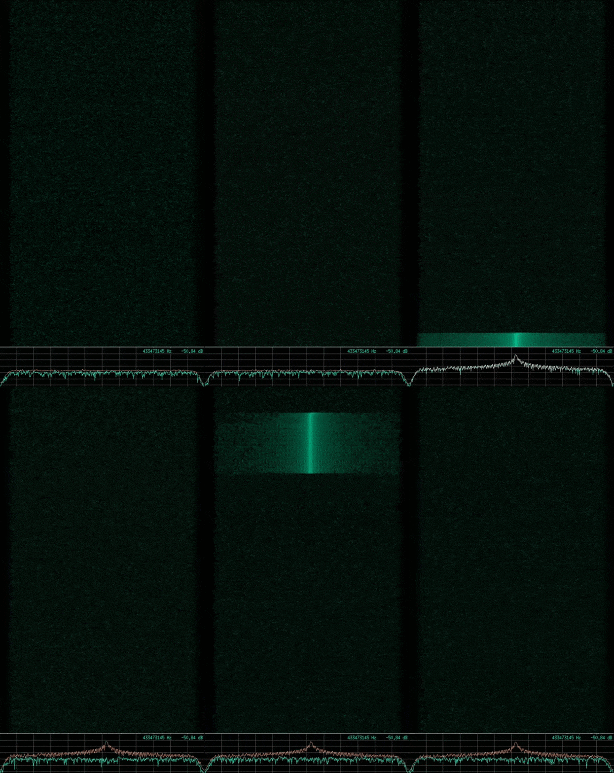
Observing this there again seems to be a number of packets sent with each click of the disarm button, however each signal seems much shorter and quicker than the doorbell remote. It is a little difficult to see, but pausing the output and zooming in to the time domain in the waterfall plot, we are able to better discern the signal. This is shown below.

From this, we are able to determine the frequency, see that it has a narrow bandwidth, and is looking very similar to the doorbell remote signal. Taking a look at the at the waveform, we see the following.

This is now much easier to see a complete packet, and the modulation is again PDM. The packet appears to be more well-formed than the doorbell, and appears to have a preamble, the initial seven long pulses, and a trailing sequence of short pulses. The data in between must represent the button pressed, as there are separate buttons for arm and disarm, along with a few others.
Each packet in the sequence that is sent with a click of the disarm button is the same, but one would expect that this packet would be different to packet sent in another key press. Let’s take a look at another press of the same disarm button.

Exactly the same.
This security system suffers from the same security vulnerability with both the doorbell and garage door remotes, I can simply record and replay this signal in a replay attack to disarm the security system of the home, business, or wherever this system is implemented. To prevent this issue, this should really be a rolling code system, where the coding of the signal changes on each press of the remote’s button.
This could be further analysed by trying different buttons and observing the changes, however for the purpose of this discussion, I went no further.
Just out of curiosity let’s take a look at 2.4 GHz WiFi to see some more complex signals and modulation.
Using baudline again to observe a portion of the WiFi frequency range, we can see the following.
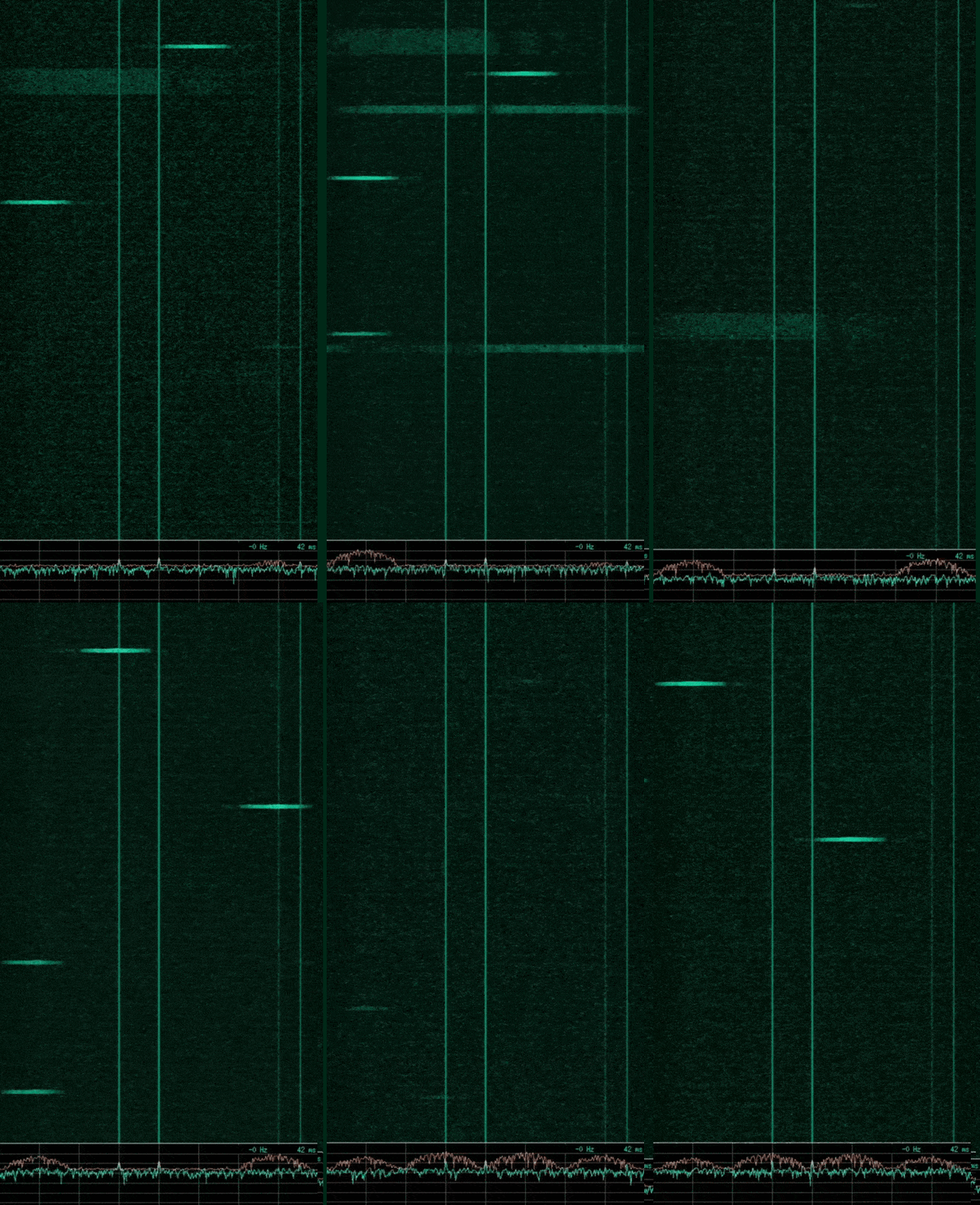
From this we can see flashes of wireless packets in four distinct channels. Peak Smoothing was enabled to show the wide bandwidth of each channel in the spectrum display at the bottom of the image. This wide frequency bandwidth of each signal is due to WiFi using spread spectrum schemes such as DSSS.
Decimating the input to view one channel, then looking at the waveform of the signal, we see the following.

This is an example of a signal that is much more difficult to determine the modulation in use visually. OSINT would be necessary in this case, and looking up WiFi modulation will show you that the more complex forms of QAM is used.
Ultimately to conduct a proper reverse engineering effort on an RF signal using SDR, requires some better understanding of RF engineering and the use of GNU Radio Companion to properly demodulate the signal. Other possibilities are to find already made GNU Radio workflows, or other software, that can demodulate the RF signal with its particular characteristics. This leaves the initial digital data, which may be further analysed using regular software reverse engineering techniques.
We looked at some RF theory to get a good basic understanding of what RF is, how data is transmitted using RF signals, and discussed some common analogue and digital modulation schemes that are the basis of more complex modulation. We briefly described SDR, including some hardware and software SDR tools that are useful for RF signal analysis and reverse engineering, along with tips for using those tools to capture and view RF signals. We identified a good methodology for attempting to reverse engineer and understand wireless protocols, and finally, we looked at the RF signals produced by some common devices in an effort to determine their characteristics, and identified some security issues along the way.
Although this discussion is not exactly a deep guide on reversing RF signals with SDR, hopefully you have learned something, or at least found it an interesting read.
Intro to SDR and RF Signal Analysis

March 2025 - New Method to Leverage Unsafe Reflection and Deserialisation to RCE on Rails
October 2024 - A Monocle on Chronicles
August 2024 - DUCTF 2024 ESPecially Secure Boot Writeup
July 2024 - plORMbing your Prisma ORM with Time-based Attacks
June 2024 - plORMbing your Django ORM
January 2024 - Keeping up with the Pwnses
elttam is a globally recognised, independent information security company, renowned for our advanced technical security assessments.
Read more about our services at elttam.com
Connect with us on LinkedIn
Follow us at @elttam